USB-C Charger Ripple Reports: Which Measurements Can You Compare?
A smaller ripple number is useful only when you know what was measured. Keep the charger’s operating conditions and the laboratory’s measurement setup beside every result.
Compare USB-C charger ripple values only after matching the operating conditions and measurement setup. For an accessory buyer, ranking two reports with missing conditions risks the wrong purchase decision. A missing bandwidth setting or an unspecified output mode leaves that decision open.
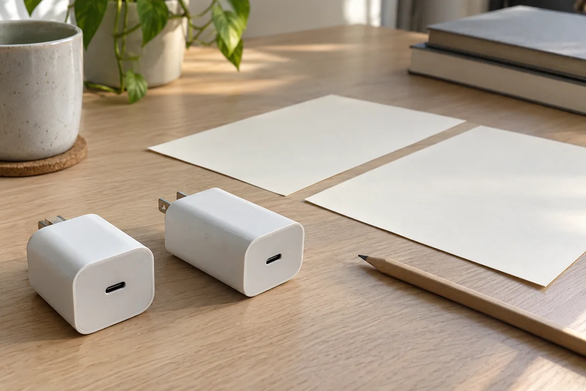
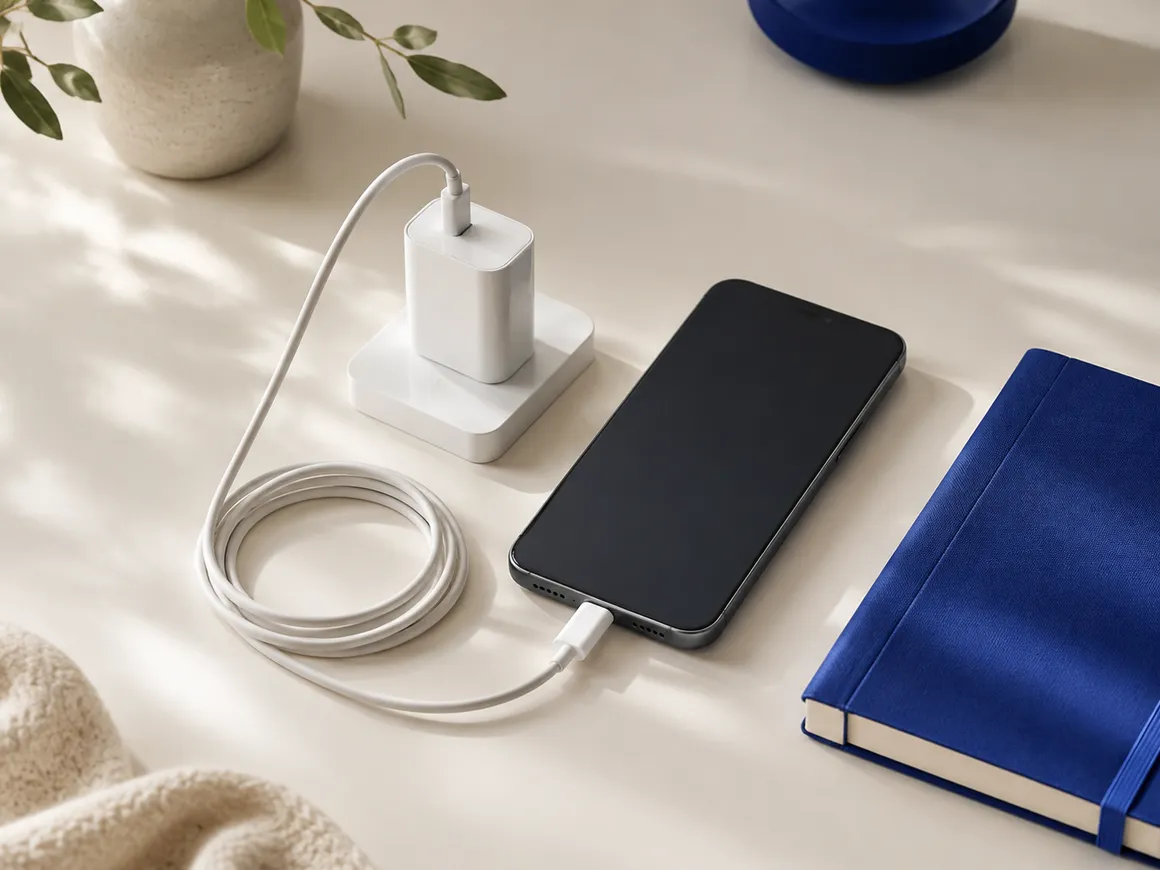
Two white single-port chargers sit beside blank sheets and a pencil on a wood desk.
Copy this power supply ripple measurement checklist
Use one column per report. Copy conditions from the report itself, with a page or capture reference. Leave missing information blank or write Unknown / verify on the unit. The empty cells below are a working record, not results for any charger.
Scroll horizontally to see all columns if needed.
| Report field | Report A | Report B | Evidence to retain |
|---|---|---|---|
| Charger model, hardware revision and sample identifier | ________ | ________ | Report identification and label photo |
| Laboratory, report date and method revision | ________ | ________ | Full report and method reference |
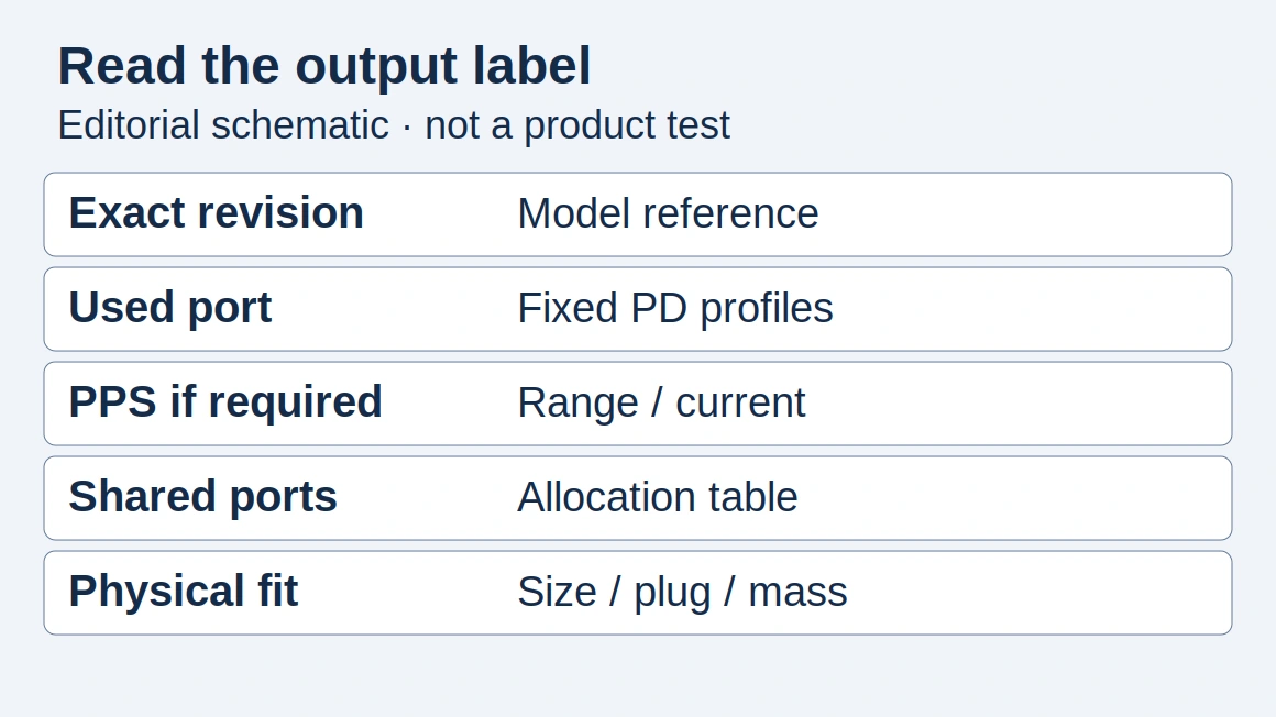
| Selected USB-C port and actual output mode | ________ | ________ | Negotiated mode record; fixed or programmable operation |
| Output voltage and load current during capture | ________ | ________ | Setpoints and recorded operating values |
| Load type and state | ________ | ________ | Electronic load or device; steady load or load change |
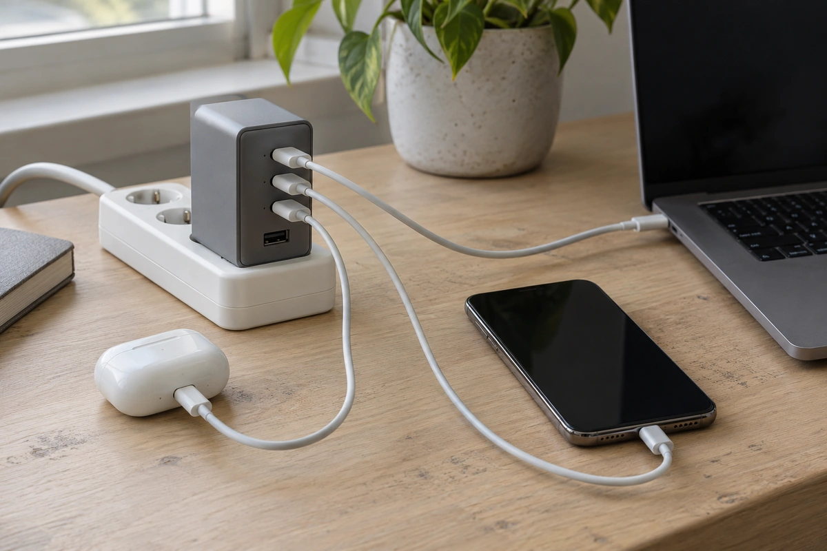
| Other occupied ports and their loads | ________ | ________ | Port connection record |
| AC input voltage/frequency and temperature conditions | ________ | ________ | Test conditions and stabilization record |
| Cable, breakout fixture and exact measurement point | ________ | ________ | Setup photo or connection drawing |
| Probe model, attenuation and signal/return path | ________ | ________ | Probe details and connection close-up |
| Oscilloscope model, input impedance and sensitivity | ________ | ________ | Instrument settings and noise-floor check |
| Bandwidth limits, external filters and added capacitors | ________ | ________ | Values, locations and filter settings |
| Coupling or offset method | ________ | ________ | AC/DC setting, offset and relevant filter information |
| Acquisition mode, timebase, sample rate and observation interval | ________ | ________ | Capture settings and averaging, if used |
| Result, units and definition | ________ | ________ | Peak-to-peak or RMS; ripple alone or ripple plus noise |
| Acceptance criterion and its source | ________ | ________ | Applicable specification, revision, clause and test conditions |
Our recommendation is to resolve missing conditions before using a report to choose between products. A blank field does not establish that a charger failed; it establishes that the report has not answered that part of the comparison.
Match the USB-C operating state first
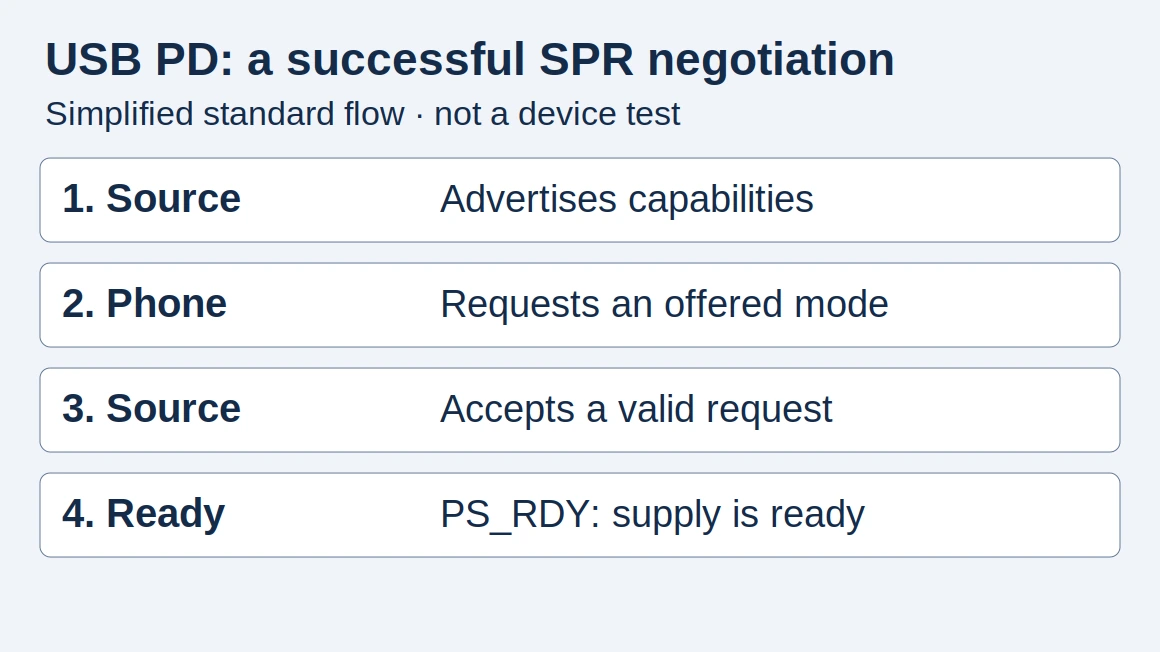
Record the output mode used during the capture, rather than copying the maximum wattage on the box. USB-IF’s Power Delivery overview explains that devices can negotiate the power they need. The USB-C PD guide explains how the available profiles, device request and cable fit together.
For this worksheet, ask the laboratory to identify the selected port, whether the output was fixed or programmable, the voltage during acquisition and the load current. For a programmable-mode capture, retain the requested operating point and whether it remained steady. “USB-C charger tested” leaves those fields unresolved.
Keep a steady-load ripple capture separate from a trace taken during a load change. Ask which event the reported maximum belongs to. Also record other connected devices: the multiport power-sharing guide explains why the port combination belongs in the operating record.
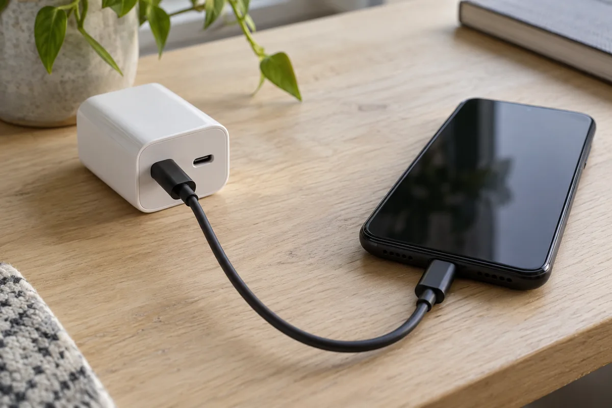
A black cable connects a white two-port charger to a phone with its screen off; the second charger port is empty.
Treat input supply, temperature and stabilization as comparison fields too. These are editorial record-keeping recommendations: this page specifies no universal warm-up duration or ambient temperature. Ask for the method the laboratory actually followed.
Check where and how the signal was measured
Ripple is the AC variation on a DC output. Texas Instruments’ SSZTB25 article shows that an extended probe ground loop can pick up noise. Analog Devices’ AN-1144 likewise demonstrates switching-transient artifacts caused by a long ground lead.
That makes the connection photo useful evidence, rather than decoration. Ask where the signal and return connected, which probe was used and how its return path was arranged. A screenshot with a number but no connection details leaves a plausible source of measurement error unresolved.
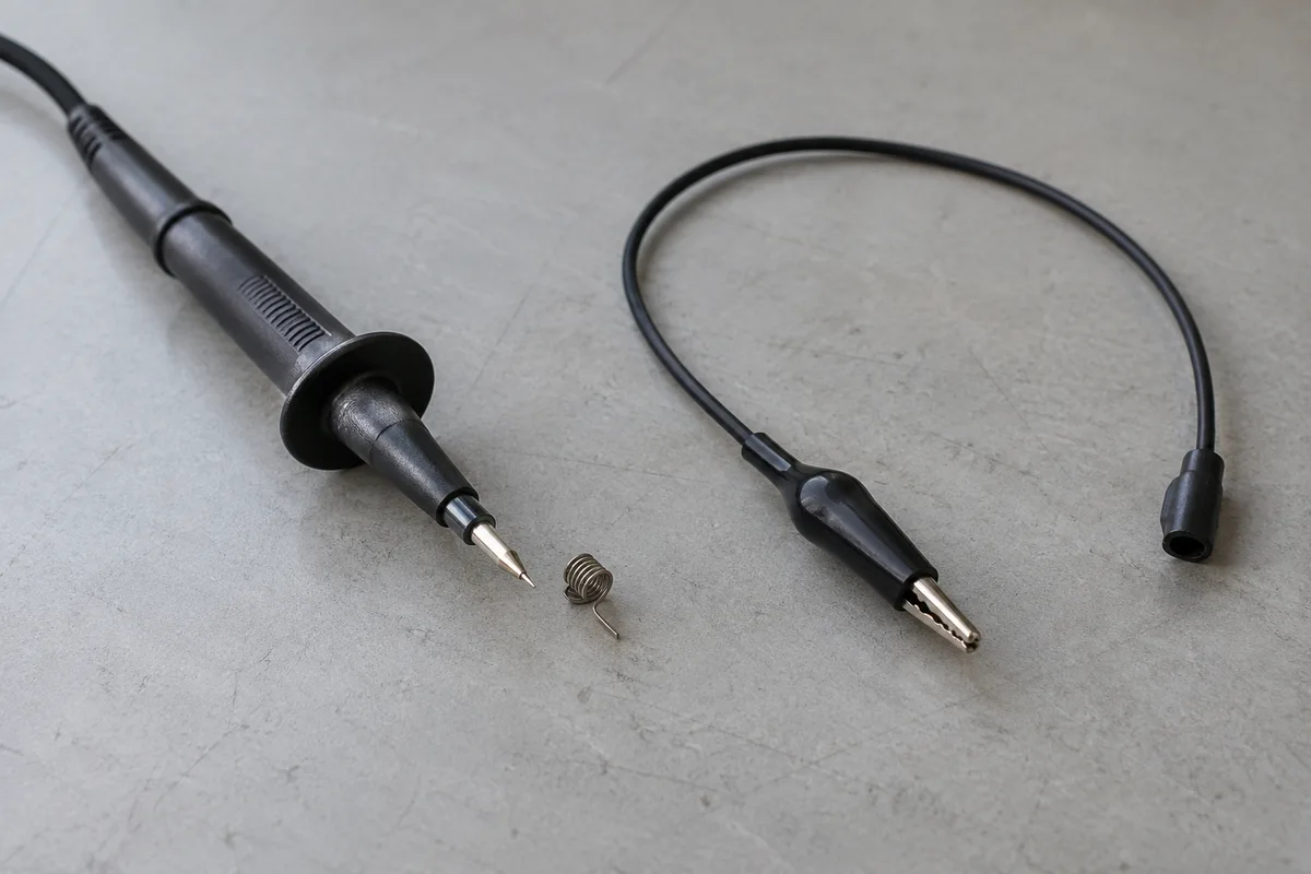
A black probe, a small metal ground spring and a separate looped ground lead rest on a gray workbench.
The measurement point matters as well. Flex’s Design Note 022, page 3, discusses distribution effects, external capacitance and probe position. Applied to a USB-C report review, our recommendation is to distinguish a measurement at the charger connector from one at the far end of a cable or breakout fixture. Retain any added capacitor or filter in the record. Do not assume two fixtures are equivalent because they both connect to USB-C.
These manufacturer notes discuss converters and evaluation circuits. Their probing examples are reasons to request evidence from a qualified laboratory; they are not instructions to open a mains charger or a USB-C compliance fixture specification.
Match bandwidth, coupling and the meaning of the number
Bandwidth: Flex DN022 describes several filtering methods, including a 20 MHz bandwidth limit, and shows that the selected method changes its example readings. That is a documented measurement condition, not a universal pass/fail limit for USB-C chargers. If one report uses a bandwidth limit and another leaves it unspecified, request a matched method before ranking their results.
Coupling and sensitivity: Tektronix’s probing application note explains that AC coupling blocks the DC component and can also exclude slow drift. It also discusses probe attenuation and sensitivity when observing small ripple signals. Record coupling, offset, probe attenuation and instrument settings; ask how the lab checked its measurement noise floor. An AC-coupled ripple capture alone does not establish the DC output level.
Units and content: Peak-to-peak records the span between the observed minimum and maximum; RMS is a different measure. Retain the exact statistic and units. Also ask whether switching spikes are included: Flex DN022 distinguishes the ripple component from higher-frequency noise that can add to a combined peak-to-peak reading. Do not silently turn a “ripple and noise” figure into “ripple only.”
Preserve the acquisition mode and observation interval beside the screenshot. For this checklist, those fields document what the lab observed; the page does not prescribe a sample rate or an averaging setting. A cropped image without its settings is insufficient evidence for a close comparison.
Decide whether the reports are comparable
Scroll horizontally to see all columns if needed.
| What the evidence shows | Decision | Next action |
|---|---|---|
| Both reports document equivalent operating states, measurement points, methods and result definitions | Compare for those stated conditions | Keep the conditions beside the numbers; do not extend the ranking to untested modes |
| A condition is missing, such as probe return path, bandwidth or negotiated mode | Insufficient evidence | Request the missing record or a matched repeat test |
| Conditions are known to differ, such as different ports, loads or filters | Different tests | Ask the laboratory for results under one agreed method |
| A supplier writes “pass” without identifying the criterion | Pass claim cannot be checked | Request the specification, revision, clause and applicable setup |
Hypothetical report review: Report A documents a fixed output, a steady electronic load and a stated bandwidth limit. Report B says only “maximum output, low ripple.” Even if B prints a smaller number, its operating mode, load and measurement chain remain unknown. Record “insufficient evidence” and request those details. This example assigns no readings to either product.
Comparability is narrower than product approval. A ripple result does not, by itself, establish electrical safety, charging speed, battery life or the cause of a device fault. For the wider purchase record, use the GaN charger specification checklist and the Charging & Power topic guide.
Ask your supplier for a complete report record
Copy this request and fill in your model and intended operating state:
Please provide the complete laboratory ripple/noise report for model and revision ________, sample ________. Identify the selected port, actual USB-C output mode, voltage, load current, other occupied ports, AC input and temperature conditions. Include the measurement point and fixture photo, probe and return-path details, oscilloscope settings, bandwidth and external filtering, coupling or offset, acquisition settings, units and result definition. For any pass/fail statement, identify the applicable specification and clause. Mark conditions that were not recorded as unknown.
Send that request to your own supplier or testing laboratory. Keep the returned evidence with the purchase specification; do not fill missing cells from another model’s report.
How this guide was prepared
Desk research with AI assistance, using primary documents fetched on 16 October 2026. The report worksheet and comparison decisions are editorial recommendations derived from documented measurement limitations. No charger was opened or tested for this guide; the photographs contain no measured results. Unit-specific readings and acceptance limits remain unknown until supported by the relevant laboratory report and applicable specification.
Sources and further reading
- Testing switching power supplies: output-voltage ripple (SSZTB25) — Texas Instruments. Accessed .
- Design Note 022: Output Ripple and Noise Measurement Methods for Flex Power Modules — Flex Power Modules. Accessed .
- AN-1144: Measuring Output Ripple and Switching Transients in Switching Regulators — Analog Devices. Accessed .
- Probing Techniques for Accurate Voltage Measurements on Power Supplies with Oscilloscopes — Tektronix. Accessed .
- USB Charger (USB Power Delivery) — USB-IF. Accessed .
Found an error? See our corrections policy and research methodology.